During use, the crankshaft is subjected to great gas burst pressure, inertial force impact and centrifugal force. In addition to wear characteristics, it can also suffer abnormal damage, scratches, burns, cracks on the journal surface, as well as crankshaft deformation, breakage and other faults or accidents.
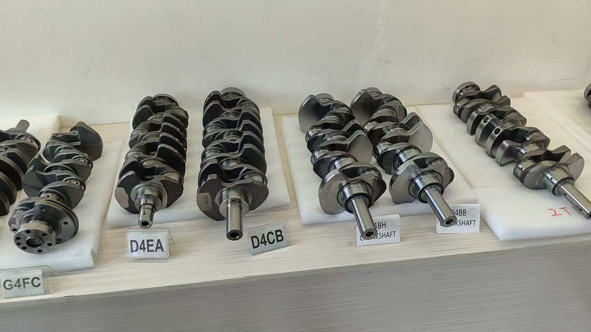
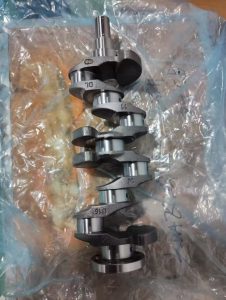
The crankshaft and flywheel assembly mainly consists of the crankshaft, main bearings, and flywheel. The crankshaft’s function is to convert the force transmitted from the connecting rod into torque, which is then output as power through the flywheel and drives the various mechanisms and systems of the diesel engine via gears or pulleys. The crankshaft comprises five parts: main journals, connecting rod journals, cranks, the front end of the crankshaft, and the rear end of the crankshaft. The main journals are supported by the main bearings. The connecting rod journals rotate around the centerline of the main journals. The cranks connect the main journals and the connecting rod journals. One connecting rod journal and the cranks at both ends form a crankshaft crank. A counterweight is added in the opposite direction of the crank to counteract the centrifugal force during crankshaft rotation, thus reducing diesel engine vibration.
There is an oblique oil passage connecting the main journals and the connecting rod journals. Some diesel engine crankshafts have a centrifugal cleaning oil chamber in the connecting rod journal section. When the crankshaft rotates, impurities and colloids in the oil entering the chamber are thrown onto the chamber wall, and the purified oil enters between the connecting rod journal and the bearing. The machined hole in the clean oil chamber is sealed with a screw plug. After a period of use, the screw plug should be unscrewed and the oil chamber cleaned. The crankshaft front end is equipped with a starter pawl, crankshaft timing gear, and pulley. The crankshaft rear end has a flywheel receiving plate, which is connected to the flywheel by bolts.
Common Crankshaft Damage

1. Crankshaft journal wear
After the crankshaft journal wears, the clearance between it and the bearing increases, resulting in abnormal noises during operation and a deterioration in working condition. The main causes are: ① Insufficient engine oil or the presence of hard abrasives in the oil, or deteriorated oil containing acidic substances.
② An excessively large or small clearance between the journal and the bearing prevents oil film formation, leading to dry friction and premature wear.
③ Prolonged overloading of the diesel engine, or operation under overheating conditions, will cause rapid wear.
④ During crankshaft rotation, centrifugal force causes mechanical impurities in the engine oil to deviate towards the oil holes, becoming abrasives and causing uneven journal wear, resulting in taper.
⑤ Bending or twisting of the connecting rod and misalignment of the cylinder liner cause uneven force distribution on the crankshaft, also resulting in taper.
2. Scratches or scoring on the surface of the crankshaft journal.
The main causes are: ① Inadequate cleaning during assembly allows impurities, metal particles, and other abrasive particles to enter the diesel engine. ② Failure to change the lubricating oil in the oil pan on time allows larger abrasive particles, such as metal particles, to mix into the gaps between the bearing shells and journals, scratching and damaging the friction surfaces. ③ Improper maintenance of the air filter increases the wear clearance of the cylinder liner, piston, and piston rings, allowing abrasive particles such as sand and impurities to be drawn into the cylinder with the air, burned, and then discharged into the oil pan, circulating into the clearance between the journals and bearings.
3. Crankshaft Journal Burns Burned journals show bluish erosion marks.
Burning wear on the crankshaft journals is caused by bearing failure. In this situation, severe friction occurs between the journal and the bearing shell, the lubricating oil film is destroyed, causing adhesion, and the temperature rises sharply, causing the journal surface to oxidize and turn blue. The surface hardness of the journal decreases, and bearing alloy fragments often adhere to it.
4. Cracks on the Crankshaft Journal Surface
Crankshaft cracks often occur at the fillet transition between the crankshaft and journal, and at the oil hole. The former is a radial crack, which is extremely dangerous and can easily cause crankshaft breakage and major engine failure; the latter is an axial crack, which develops axially along the oil hole. The main causes of cracks are manufacturing and repair defects and improper use: ① During use, poor journal surface roughness, with defects such as indentations, scratches, corrosion, and pits, are stress concentration points. If these are not eliminated in time, fatigue cracks will first originate and develop here. ② Insufficient lubrication can lead to severe bearing failure, causing axial cracks. ③ Long-term use can cause metal fatigue transition on the journal surface, leading to circumferential cracks. ④ After grinding, if the shoulder fillet radius is too small, the transition is not smooth, or the surface roughness is poor, stress concentration will occur. ⑤ When repairing the journal by welding, excessive residual stress is generated on the surface, causing cracks.
5. Crankshaft Deformation
Crankshaft deformation typically occurs through bending and torsional deformation. Excessive crankshaft deformation leads to accelerated wear on itself and connected parts, increased fatigue, and ultimately, crankshaft breakage and excessive mechanical vibration. The causes of crankshaft deformation can be categorized as non-human-caused or human-caused. Non-human-caused deformation includes: deformation due to cyclic gas pressure, reciprocating inertial forces, centrifugal forces from rotational motion, and mechanical braking forces.
Human-caused deformation is primarily due to violations of operating procedures and accidental mechanical failures: ① Aggressive starting under heavy loads. ② Rough operation of the diesel engine, subjecting the crankshaft to sudden impact loads. ③ Overspeeding or running away with the engine, using excessively forceful braking to shut it off immediately. ④ Bearing seizure due to insufficient lubrication or insufficient bearing clearance, resulting in excessive torque on the crankshaft. ⑤ Severe deformation and misalignment of the cylinder block main bearing housings.
6. Crankshaft Breakage
Crankshaft fracture is an accidental damage to a diesel engine, and its causes are complex. Fracture locations include: ① At the crank arm where two adjacent fillets of the crankshaft journal meet. ② At the 45° angle along the oil passage of the connecting rod journal. ③ At the root of the connecting rod journal or the main journal. ④ At the keyway of the tapered surface where the flywheel is mounted. All causes of surface cracks in the crankshaft journals and causes bending or twisting of the crankshaft can lead to crankshaft fracture. In addition, the following are also possible causes:
① Poor crankshaft material, manufacturing defects, inadequate heat treatment quality, or machining roughness failing to meet design requirements.
② Flywheel imbalance, misalignment between the flywheel and crankshaft coupling, disrupting the balance between the flywheel and crankshaft, generating significant inertial forces, leading to crankshaft fatigue fracture.
③ Excessive weight difference in the replaced piston and connecting rod assemblies, causing inconsistent explosive forces and inertial forces in each cylinder, resulting in unbalanced forces on the crankshaft journals and causing crankshaft fracture.
④ Insufficient tightening torque of flywheel bolts or nuts during installation can cause loosening at the flywheel-crankshaft connection, leading to flywheel imbalance and generating significant inertial force, potentially causing crankshaft breakage.
⑤ Severe wear of bearings and journals, resulting in excessive clearance, can cause sudden changes in engine speed, subjecting the crankshaft to impact loads.
⑥ Prolonged use and more than three grinding cycles can reduce the journal size, making the crankshaft more susceptible to breakage.
⑦ Premature fuel injection timing can cause rough engine operation; poor throttle control during operation, resulting in unstable engine speed, all contribute to significant impact loads on the crankshaft, making it prone to breakage.
7. Damage to other parts of the crankshaft: Wear on the crankshaft oil-blocking threads or shoulders, wear on the front keyway, damage or stripping of the starter claw threads, etc.
Preventive measures
(1) Perform timely maintenance to ensure the quality of lubricating oil; during repair and assembly, ensure the correct clearance between the journal and bearing shell; avoid prolonged overload operation of the engine.
(2) When overhauling the engine, carefully inspect the stress concentration areas of the crankshaft for cracks. If possible, use instruments for magnetic particle inspection. Repair any damage promptly.
(3) When polishing the crankshaft, maintain the transition radius at the connection between the journal and crankshaft. Never grind it into a sharp angle, otherwise, significant stress concentration will occur, leading to crankshaft breakage.
(4) Pay attention to the balance of the crankshaft, flywheel, and clutch. When the clutch assembly is installed on the flywheel, shims should be placed at its fixing bolts to prevent vibration and avoid deteriorating the crankshaft’s working conditions.
(5) Regularly check the preload of the fixing bolts for bearings and flywheels. When tightening the main bearing cap nuts during crankshaft installation, tighten them multiple times according to the specified torque and sequence.